
Verification of the OR gate truth table using diodes, resistors, LEDs, and a supply shows output high if any input is high, with procedure and precautions.
Apparatus
-
Two semiconductor diodes (SD-1)
-
Power supply (5 V)
-
4.7 kΩ resistor
-
LED (indicator)
-
Two two-way (SPDT) keys
-
Breadboard and connecting wires
Theory
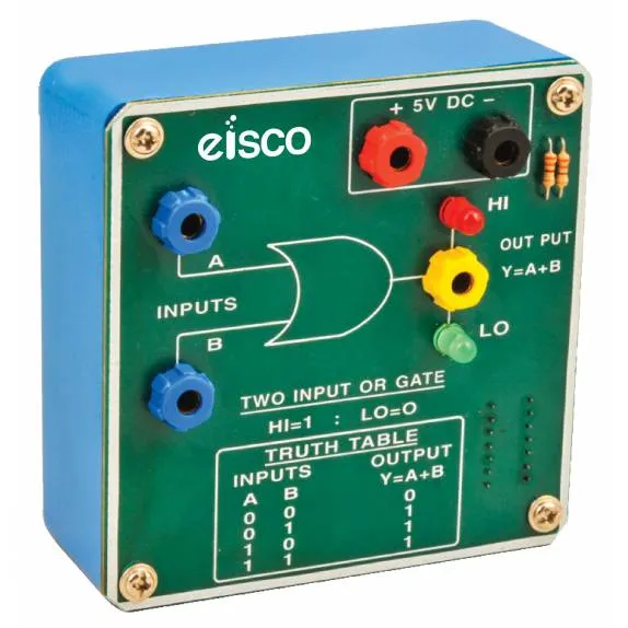
An OR gate is a logic circuit that provides a HIGH output (1) when any input is HIGH. Its Boolean equation is F = A + B. Thus, the output remains LOW only when all inputs are LOW.
When a diode connected to an input becomes forward-biased, current flows through the resistor and lights the LED. Otherwise, the diode remains off. Therefore, the LED indicates logic “1.”
| Input | Output | |
| A | B | F=A+B |
| 0 | 0 | 0 |
| 0 | 1 | 1 |
| 1 | 0 | 1 |
| 1 | 1 | 1 |
Circuit Description
First, connect both diodes so their anodes go to inputs A and B. Then, join their cathodes and connect them to one end of the resistor. Attach the other end of the resistor to +5 V through the LED. Finally, connect the common ground to represent logic 0.
Procedure
Step 1: Initial Setup
Begin by checking all diodes and cleaning wire ends.
Afterward, assemble the circuit on the breadboard as shown in the diagram.
Next, connect the power supply and ensure the polarity is correct.
Finally, keep both input keys open before testing.
Step 2: Verification of Truth Table
-
Case 1 — A = 0, B = 0:
When both A and B are at ground potential, neither diode conducts. As a result, no current flows and the LED remains OFF. Hence, F = 0. -
Case 2 — A = 0, B = 1:
Keep A grounded and apply +5 V to B. Consequently, diode B becomes forward-biased, current flows, and the LED glows. Therefore, F = 1. -
Case 3 — A = 1, B = 0:
Now, reverse the previous condition. Input A receives +5 V, and B stays grounded. Thus, diode A conducts while diode B remains off. The LED lights up again, confirming F = 1. -
Case 4 — A = 1, B = 1:
When both inputs are HIGH, both diodes conduct simultaneously. The voltage drop across the diodes is negligible. Consequently, the full voltage appears across the resistor, and the LED glows. Hence, F = 1.
Observations
-
Record LED state (ON/OFF) for each input pair.
-
The readings should match the OR gate truth table.
Results
The OR gate operation is verified successfully. Furthermore, the LED lights whenever at least one input is HIGH, which confirms the Boolean expression F = A + B.
Precautions
-
Always check diodes before use.
-
In addition, clean the connecting wire ends to ensure good contact.
-
Avoid disturbing the setup during observations.
-
Use a resistor of the correct value (4.7 kΩ) to protect the LED.
-
Finally, verify connections carefully before powering the circuit.
Viva Voce
Q1. What is a truth table?
A truth table lists all possible input combinations along with their corresponding outputs.
Q2. What is a logic gate?
A logic gate is an electronic circuit that performs a Boolean function.
Q3. Why is the OR gate called “any-or-all”?
It gives a HIGH output if any or all inputs are HIGH.
Q4. When is an OR gate’s output LOW?
The output is LOW only when all inputs are LOW.
Q5. What is an LED?
An LED is a semiconductor diode that emits light when forward-biased.